Preparing for a Cable Trunking Project
Assessing Site Conditions and Layout
Standing in a dusty Cape Town factory, I once watched a contractor measure a wall three times and still get the trunking installation wrong. The lesson? Site conditions are not a suggestion; they are the entire plot.
Before you buy a single metre of PVC, assess the layout with the suspicion of a customs official. Check for uneven surfaces, hidden pipes, and the inevitable corner that swallows your clips.
- Measure the actual path, not the straight line.
- Look for existing cables that will migrate into your lane.
- Confirm wall material: brick, drywall, or reinforced concrete.
Your trunking installation will either fit like a glove or fight like a cat. Choose the former by walking the route twice, once in the morning light and once in the afternoon shadow. That second pass will reveal the crooked floor that no spirit level ever admitted.
Choosing the Appropriate Trunking Material
Sixty percent of premature cable faults begin with an underplanned trunking installation. Before routing a conductor, calculate the total cable cross section. Leave 40 percent spare capacity for future additions. Verify temperature range, especially where salt air corrodes cheap metallics.
Material choice dictates longevity. PVC suits dry interiors, its flexibility easing corners. Polycarbonate resists impact and UV. Galvanised steel handles heat, moisture, and abuse.
- Check fire rating for vertical runs.
- Confirm UV stabiliser content for exposed areas.
- Match fixing centres to the wall substrate.
Ordering material for a trunking installation begins with a checklist. Compare prices per metre, but factor in labour. A flimsy clip that fails after six months costs more than a premium bracket. I once watched a contractor save R200 on trunking, then spend R2,000 redoing it! Keep spare parts in the same batch, because dye lots vary. A robust installation endures South African sun without cracking.
Calculating Dimensions and Cutting Accuracy
A 5mm error at the base of a trunking installation becomes a 15mm gap once the lid snaps on. Precision starts before the saw touches the section. Mark each length directly on the base, not on the wall. Transfer dimensions with a sharp pencil and a square. Use a fine-tooth saw for PVC. Deburr every cut edge with a file. A rough edge tears cable sheaths during pulling, and that leads to premature faults.
Corners demand patience. Each internal bend removes material from the base, never the lid. Treat each wall as its own run. Total lengths tempt you, but sequence is safer.
- Add a 3mm expansion gap per 3m of run.
- Number each cut base and its matching lid.
- Check mitres against the wall angle before fixing.
Cutting accuracy protects your labour. A wasted length means a second trip to the supplier. In a tight budget, that matters.
Compiling Tools, Fasteners, and Safety Equipment
Preparation decides the outcome before the ladder goes up. Most delayed projects stall on a missing component, not a difficult wall. Assemble the tools that matter: a fine toothed saw, a sharp knife, a chisel for box cut-outs, and a spirit level you trust. These essentials vanish quietly from site boxes.
- Galvanised wall plugs and screw anchors for masonry
- Cavity fixings for drywall
- Brass screws for switch plates
- A residual current device at the supply point
- Insulated tools rated for 1000V
Fasteners must suit the substrate; Highveld humidity corrodes mild steel screws. Use zinc plated or stainless fixings throughout. Safety equipment deserves equal attention. Keep a fire extinguisher rated for electrical fires and test your voltage tester before each job. A trunking installation rarely fails on skill. It fails on poor foresight.
Executing the Mounting and Routing Process
Marking Fixing Points and Drilling Holes
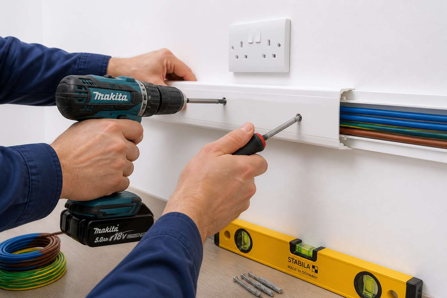
One misplaced chalk line can turn a clean trunking installation into a costly error. There is no room for guesswork. I mark each fixing point after checking the run with a spirit level, always accounting for the building’s true vertical. Fixing intervals follow a deliberate rhythm:
– Near every joint and corner
– At consistent spans to prevent sagging
– Away from hidden cables or voids
Only after these points are approved by eye and level do I pick up the drill. The bit must meet the wall at ninety degrees. Any drift invites a cracked base or a loose screw that will mock you later. The dust settles, and you test each hole by hand before driving the first fastener.
Fitting the Base Section and Laying Cables
“Zip ties are cheap. Ripping out a wall to fix a pinched cable is not.” That thought often guides the hands of a seasoned electrician. The mounting of the base section is where the patience of the preparation phase pays off. I start at the corner, pressing the channel firmly against the wall, aligning the first screw hole with the drilled point. Each fastener is driven home with a steady hand, but I never tighten it fully until the next section is clipped into place. This allows for a slight adjustment, a gentle flex of the plastic to accommodate a subtle undulation in the plaster. A rigid line here invites stress fractures later.
Once the base is secured, the routing process begins. This is the quiet, methodical part of a trunking installation. You lay the cables in with respect, not force. The bend radius of the wire is sacred; crushing it against a sharp internal edge creates a hot spot that could fail years down the line.
The sequence often dictates the safety of the entire system:
1. Run the data and signal cables first, keeping them as far from the power conductors as the trunking width allows.
2. Lay the heavier mains cables in last, laying them on top so they do not crush the more delicate cores.
3. Leave a little slack at each planned outlet point, a small loop that allows for future termination without pulling the whole system taut.
The lid clicks on with a satisfying snap only if the internal wiring is neat. If the cables are piled high and tangled, the cover will bow, and the joints will gape. I take my time here. A neat bundle is a safe bundle, and a safe trunking installation is one that you can forget about, which is exactly the point.
Securing Cables with Clips and Ties
A cable that moves after the lid is closed is a problem you will chase for years. In trunking installation, the securing stage settles everything. I use nylon clips at every change of direction and cable ties spaced along straight runs. The ties hold the bundle, the clips fix its position.
Tension is the hidden risk. A tie cranked too tight compresses the insulation. I pull until the bundle is firm, then I stop. The right pressure is firm without being strained.
Placement rules I follow:
- Clips at every bend and within 20 mm of outlets.
- Ties every 300 mm on horizontal runs, 200 mm on vertical.
- Extra tie where power and data run parallel.
When the last tie is trimmed, I slide my hand along the bundle. If anything shifts, I add another clip.
Attaching Covers and Accessories
The final click of a trunking lid is a satisfying sound. It tells you the mounting and routing process has reached its end cleanly. If you have to lean on the cover, stop! Something underneath is pushing upward, and that will not improve with time.
Accessories deserve the same attention. Couplers bridge the gaps between sections, and end caps finish the run without leaving sharp edges. In a trunking installation, these small parts determine whether the job looks complete. I test each fit before committing. A cover that fights you today will be a persistent annoyance tomorrow.
- Check the cover alignment from both ends.
- Press the centre first, then work outward.
- Confirm each accessory clicks or screws flush.
Handling Corners, Joints, and End Caps
Corners end more trunking installation work than tangled cable ever will. A 90 degree internal corner looks simple until you bring a saw to it. I cut the back wall at an angle, then the lid separately. This method keeps the base aligned while the cover flexes into place with minimal persuasion.
Joints need a coupler, but couplers vary. Some sit flush, others protrude a little. I slide the coupler halfway into one section, seat the next section, then check the seam with a fingernail. If it catches, I adjust rather than hammer. External corners demand a mitre block and patience. I verify the angle twice, make the cut, and keep offcuts nearby for practice runs. End caps finish the run with a quiet click. No trunking installation feels complete until those caps seat properly.
Electrical Conformity and Protective Measures
Meeting Wiring Regulations and Standards
In the realm of electrical work, conformity is not a bureaucratic hurdle but the very fabric of safety. A trunking installation that ignores the SANS regulations is akin to a guest arriving at a formal dinner in beachwear. It may technically function, but the impression is disastrous, and the consequences can be far more permanent than a social faux pas. The protective measures we employ are the quiet sentinels that guard against fire, shock, and the slow degradation of your property’s integrity.
The physical protection afforded by the trunking is only half the story. The other half lies in the meticulous earthing and bonding of the metallic components. A floating earth is a silent hazard, waiting for a fault to turn an innocent cover into a live conductor. Your compliance strategy must account for the specific environmental factors of the site, ensuring that the ingress protection rating of the chosen system matches the humidity or dust levels of the location. Inspections are your final courtesy call to the standards, where you verify:
– The integrity of all protective conductors.
– Correct segregation between low voltage and extra-low voltage circuits.
– The mechanical security of all cover plates and accessories.
This diligence transforms a mere cable pathway into a certified component of the building’s electrical nervous system. It is the difference between an installation that merely exists and one that performs with quiet, dependable grace. The paperwork is the record of your good manners, a formal declaration that you have upheld the contract of safety with the end-user.
Managing Cable Capacity and Heat Dissipation
Electrical capacity is not a number on a datasheet; it is a living, breathing calculation. The moment you pack a trunking installation with cables, you create a warm ecosystem, a microclimate where resistance breeds heat. That warmth is the enemy of insulation and the quiet thief of current-carrying capacity. A cable’s rating is always tempered by its environment, so the internal dimensions of your chosen pathway must account for the thermal budget of the circuits inside. The physics are unforgiving.
Consider this: a conduit that is 40% full of cables is not a practical limit, it is a thermal requirement. Exceeding that density turns your neat pathway into a slow-baking oven.
The materials of your system play their own role in the thermal ledger. Steel trunking acts as a radiator, wicking heat away from the conductors, while non-metallic systems retain more warmth, demanding a more generous fill allowance. Follow this checklist when planning for heat:
– Derate the cable current ratings based on the ambient temperature of the site.
– Check the manufacturer’s derating factors for grouped circuits.
– Factor in the thermal conductivity of the trunking material itself.
Manage the heat budget before you pull a single conductor. Every circuit added to the bundle raises the stakes, and the solution often lies in choosing a larger profile or separating the high-load feeds. The finesse is in the balance, giving each cable the air it needs to breathe. When you grant that space, the installation runs cooler, safer, and with a longevity that surpasses the hasty, overcrowded alternative.
Implementing Moisture and Dust Resistance
One unsealed gland is all it takes. Moisture seeps in, dust settles, and the circuit fails. South Africa’s climate varies from damp coasts to arid interiors, exposing every trunking installation to these threats. Conformity to SANS 10142 is mandatory, but compliance does not equal protection. The key is implementing moisture and dust resistance at every junction. IP ratings provide a guide, yet the real world demands verification. I have seen a IP66 rated box fail because the cover was not aligned. Sealing requires precision!
- Use compression glands for every cable entry point.
- Fit gaskets that match the exact trunking profile.
- Apply dielectric grease on threaded connections.
Each measure addresses a specific failure path. A properly sealed installation survives for decades. The difference is attention to detail.
Ensuring Proper Earthing and Bonding
A single faulty earth bond in a trunking installation leaves every metal surface live. The circuit keeps running until someone touches the wrong part. SANS 10142 mandates the earthing system, yet real protection demands verification of every joint.
Bonding links all exposed conductive parts to the earth electrode. That includes covers, brackets, and cable armour. Loose connections create impedance, turning a harmless touch into danger. I have seen a bonding clamp fail because the surface was painted over.
Essential checks are straightforward:
- Measure earth continuity at each joint
- Tighten every bonding clamp
- Confirm the earth conductor has no shared terminations
These steps belong at the core of safe electrical practice. Safety depends on exact torque, clean surfaces, and proper clamping.
Applying Fire-Retardant and Low-Smoke Options
I have seen fire inspections fail because a trunking installation used the wrong polymer. The material looks identical, but its behaviour under heat is the difference between a minor incident and a deadly plume.
Electrical conformity demands fire-retardant compounds and low-smoke additives. Halogen-free options release less toxic gas, while flame-retardant ratings stop the spread along cable trays.
- Check the manufacturer’s certification against SANS standards
- Verify low-smoke density for confined spaces
- Confirm that joints and fittings maintain the same fire rating
Every installation should treat these as mandatory, not optional. Protective measures only work when the entire path, from base to cover, uses compliant materials.
Planning for Future Cable Additions
The cabling that carries power and data is the nervous system of any modern building, yet the trunking installation that protects it is often the afterthought. In South Africa, where electrical storms and load-shedding place unique strain on infrastructure, planning for future additions is not clever, it is essential. A conduit that is full today is a costly problem tomorrow, requiring a complete strip down and a fresh trunking installation to accommodate a single new circuit.
Electrical conformity is not a single product choice, it is a systemic requirement. The fire-rated path must be continuous, from the base section to the final cover plate, and this includes the fixings and fasteners used. A high-specification enclosure fixed with substandard screws undermines the entire protective scheme. Planning for capacity requires a disciplined look at the spare space within the tray, often calculated at a 20 to 30 percent fill ratio to allow for heat dissipation and future growth. A rigid approach to casing sizes now avoids the tragedy of a costly rewire later.
The installation should offer a clear route for expansion, with accessible joints and removable lids that permit swift modifications. This foresight demands an element of humility, an admission that current requirements will change. Consider the following to secure a versatile system:
– Reserve spare capacity in the primary cable tray for new circuits.
– Place junction boxes at strategic intervals to allow for future branch runs.
– Document the final layout clearly for the next engineer who must navigate the system.
A truly professional trunking installation is a gift to the future, a silent system that adapts without protest. The material quality, the earthing integrity, and the fire rating of every single component must be considered as one unified system. It is this holistic view that separates a temporary fix from a permanent solution, ensuring the building serves its occupants for decades without a single moment of ugly disruption. The vision of a seamless, adaptable building starts with the humble, invisible pathway of your initial trunking installation.
Rectifying Issues and Maintaining System Integrity
Identifying Frequent Fitment and Alignment Errors
A misaligned base section can compromise an entire run. During trunking installation, I have seen covers refuse to close because fixings were driven home at an angle. That slight deviation creates a stubborn ridge.
Check for squareness before final tightening. Frequent fitment and alignment errors include:
- Spacing clips unevenly along the channel
- Drilling holes that wander off the marked centre
- Forcing joints where expansion has already shifted the line
Each fault compounds. Correcting one section often reveals another misalignment downstream. Maintain integrity by loosening adjacent fixings, realigning the datum edge, then retightening in sequence. This restores the intended geometry and prevents stress on the covers.
Correcting Loose Bases and Misaligned Covers
There is a point in every trunking installation where the job fights back. Loose bases and misaligned covers are the usual culprits. A cover that refuses to click shut is a small outrage. Ignoring it guarantees a larger one later.
The fix begins with loosening, not force. A base that sits proud at the fixing points will transfer that tension to the cover, creating a gap or a strained clip. This is the moment to reassess the sequence of your work, not to wrestle with the plastic.
A practical approach to rectifying stubborn sections involves a simple order of operations:
1. Loosen the affected base fixings, plus one on either side.
2. Re-seat the base against the datum edge.
3. Retighten from the centre outward.
4. Test the cover fit before moving on.
Patience pays off here. A straight, well-seated base accepts its cover without complaint. A rushed job produces creaks and gaps that undermine the entire trunking installation. The goal is a finished system that looks intentional, not improvised. Taking the extra minutes to correct these minor faults saves you from a major headache when the final inspection rolls around.
Conducting Routine Inspections and Debris Removal
A trunking installation collects more than cables. Dust, grit, and offcuts accumulate inside the base, and they do not stay harmless. Routine inspections are the only defence against a system that degrades quietly behind its covers.
Debris removal is not cosmetic. Metal shavings from drilling, plaster dust, and cable offcuts work their way into clips and joints, causing covers to sit proud and latches to bind. A quick sweep of the interior before sealing each section prevents these faults from becoming permanent.
- Check cover alignment at every joint and end cap.
- Vacuum or blow out debris before adding new cables.
- Inspect clip tension and base seating at fixing points.
System integrity depends on this discipline. A trunking installation that looks sound from the outside can hide a slow accumulation of contamination that undermines its performance. Regular checks keep the system honest.
Upgrading or Extending Existing Containment Runs
Reworking an existing containment network is often more demanding than a fresh fit. The consequence of a poorly planned extension is downtime, and in a commercial environment, downtime carries a direct cost. Upgrading a run means the trunking installation must be treated as a living system, not a static fixture. The old cover screws may be corroded, the base may have shifted, and the existing cable fill might be at its legal limit. Before cutting a single new section, verify the current state of the containment.
A strategic approach to expansion involves a clear sequence of actions to protect the entire network.
– Confirm the spare capacity of the existing trunking installation against the new cable load.
– Isolate the section and test for the absence of live conductors before opening the cover.
– Clean the existing joint surfaces where new couplers will seat to ensure a flush fit.
Adding length to a run is straightforward; adding value is not. The most common failure in an extension is a mismatch of thermal dynamics. Packing new datelines alongside high-current feeders demands a recalculation of grouping factors, not just a visual check. The integrity of the system rests on how well you balance the old with the new. If you are cutting into an existing base, anchor the new couplers properly and re-drill for fresh fixing points rather than relying on the old holes. This discipline keeps the trunking installation safe, compliant, and ready for the next decade of service.




0 Comments